|
|
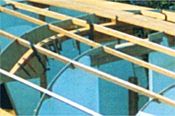
Laminated floor clamped against longitudinal framing to give it shape while the glue sets. The floors are done one at a time so that pressure from the floor does not deflect the stringers excessively.
After the glue has hardened the floor is removed and cleaned up on the workbench. It is also planed to the final taper and reshaped by hand plane where needed so that it fits snug against all stringers. It may be necessary to build it up a bit at some stringers to form a bearing surface.
We recommend that all laminating is done with resorcinol glue, not epoxy. Read more on properties of glues.
|
|
|
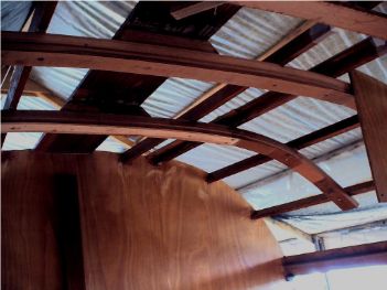
Laminated floors from below, before adding doublers, backbone spacers and keelson. This is the boat of Greg & Nikos Vouloumanos in Greece.
|
|
|
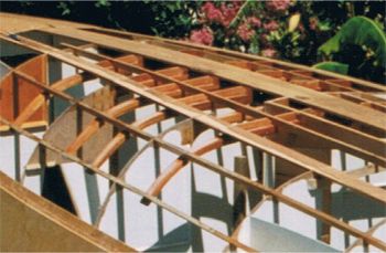
The next few photos are with all floors fitted and work proceeding toward skinning the hull.
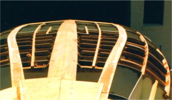
Together with the backbone, the floors form the major loadbearing structure for the ballast loads. They have to be strongly built and all possible must be done to stiffen the whole centre part of the hull.
The floors must be continuous across the width of the boat and pass through the backbone structure. Don't laminate them from short lengths of timber, each lamination must be in one piece.
|
|
|
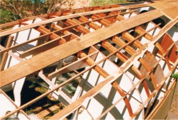
We try to tie in the floors to as much other structure as possible, to gain maximum strength from minimum weight. In this photo the engine beds are visible to the left. They are keyed into the last floor, tied into two bulkhead and bonded to the hull skin, extending the stiffness of the backbone/floor structure further aft.
|
|
|
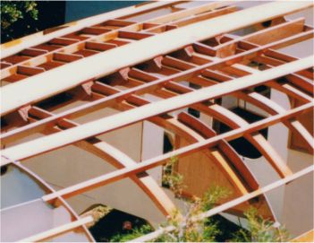
Closer detail of floors. Note these details:-
~ Doublers to floors at backbone to compensate for material lost to bolt holes.
~ Plywood fillers between floors and hull skin from backbone to tangent stringers.These stiffen the hull when heavily heeled in lumpy seas by preventing flexing of the skin. Limber holes allow water to flow alongside stringers and backbone.
~ Floor passing through engine bearers, not just notched but fully locked to each other. Engine beds are fully sealed to the skin, forming an oil dam.
|
|
|
Same stage, looking from forward.
|
|
|
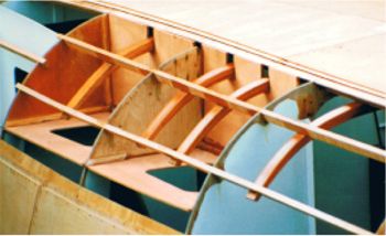
The floors pass through the settee fronts and are locked into them. The settees are structural beams, passing floor loads into 3 bulkheads. In this photo the settee fronts have been notched around the floors. The openings will be plugged with plywood and the whole junction sealed with high density epoxy filler, followed by fillets then a layer of glass tape all round. The settees also form integral water tanks, so they have to be similarly sealed against the hull skin. The result is a rigid structure to resist ballast and rig loadings very effectively.
|
|

|
Bird's-eye view of the internal structure before fitting the deck. Look carefully and you can see:-
~ Backbone all along hull centreline.
~ Laminated floors crossong over top of backbone and running into water tanks.
~ Keelson running fore/aft on top of floors, stopping at aft floor.
~ Engine beds running parallel to backbone at right of photo.
|
|
|
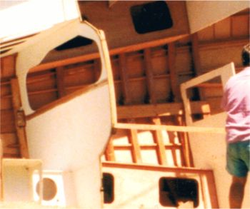
Similar view but photo taken when hull was on its side during roll-over.
In these photos you can see how much of the interior joinery I chose to build before turning the hull over. Some builders have built almost the complete interior, including painting, varnishing and fitting locker doors before turning their hulls.
|